What is Lod & Everything About it in 3D Modelling
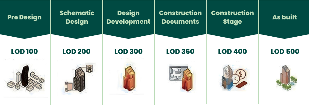
Table of Contents
Professionals in the Architecture, Engineering and Construction (AEC) sector can create dependable and intelligible BIM workflows and models throughout various project life cycles by using LOD as a reference framework. LOD 100 through LOD 500 are the six stages of development that are discussed in the article. Each level corresponds to a continual increase in the geometric and informational detail of model pieces. We will also explore the various Levels of Development in 3D modelling.
This guide explains BIM Level of Development (LOD), its history, benefits, and how LOD 100–500 shape accurate 3D modelling. It clarifies Level of Detail vs Level of Development and why standardised LODs improve coordination, reliability, and decision-making. Ideal for AEC professionals looking to create precise BIM models and streamline project execution.
What is LOD?
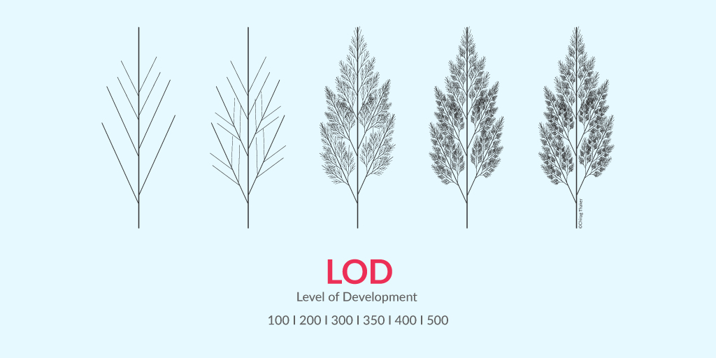
BIM Level of Development (LOD) specifies the degree of information and geometry associated with each element of a BIM model. It helps professionals understand how much information can be relied upon during the project's lifecycle, from conceptual design to final construction.
The “Level of Development (LOD) Specification” is a reference that enables professionals in the AEC Industry to develop reliable and understandable Building Information Models (BIMs) at different life cycles of their project.
Level of Detail (LOD) popularly refers to the representation of geometric information in a 3D model’s element. LOD specification allows professionals in the industry to clearly articulate how an element’s geometry and associated information have evolved throughout the entire process. It signifies the degree to which different members of the team can rely on information associated with an element.
There are six levels of development, namely, LOD 100, LOD 200, LOD 300, LOD 350, LOD 400, LOD 500. Here, LOD 100 means the model has lower geometric information compared to LOD 200.
Also Read: 10 Award-Winning Architecture Thesis Projects From Around The World
Concept and History of LOD
A good overview of the history and evolution of LOD can be found in the article “Many Faces of LOD” by Marzia Bolpagni (MACE). Drawing from that article, the first instance of LOD usage can be traced back to 2004 by a construction analysis software company, Vico Software (now part of Trimble), where they used a LOD-like system to associate digital models with the cost of a project.
The term LOD was later introduced in 2008 by AIA (American Institute of Architects). It introduced five ‘Levels of Development’ (LOD 100 - LOD 500) in the Building Information Modeling Protocol Exhibit, which was further updated in 2013. These documents became the point of reference in several countries – including Australia, Canada, Singapore, China, Taiwan, Germany and France. Other countries developed their variant specification.
The Need for Standardising the “Level of D”
There was a pressing need to standardise the “Level of D” to avoid confusion as this process was very similar across countries and construction projects. For this, concepts such as “level of detail,” “model progression specification” and “level of development ” were established.
One widely-used specification for LOD can be found in the “Level of Development Specification,” which is published and updated yearly by BIMForum and is based on specifications by the American Institute of Architects (AIA).
Here are some of the most important concepts from the BIMForum specification:
-
The level of development is stated at an object level, not at the model, since different objects can be at different levels of development across a single model.
-
The use of “development” rather than “detail” is used to indicate the degree to which you can rely on the information and not by how much detail there is.
-
Five main levels have been defined initially using a numerical label in steps of 100, theoretically allowing for intermediate levels if needed. The labels as such are rather arbitrary but represent the gradual evolution that is typically seen in a project.
Currently three major LOD matrices are being used in the United States: AIA ,BIMForum, and U.S. Army Corps of Engineers (USACE). Each one has a slightly different approach, but all of them are based on the same concept.
Benefits of BIM Level of Development
Adopting BIM Level of Development ensures accuracy, reduces errors, and enhances collaboration throughout the project. Standardized LODs improve communication, help avoid conflicts, and provide a clearer understanding of model reliability, ultimately optimizing project execution.
- It helps all the stakeholders involved in a project to work on the same page, so that there are no inconsistencies that hamper a project’s prospects.
When all the stakeholders are on the same page, communication and collaboration becomes easier and faster. - With the help of standardised specifications and detailed information about all the elements, designers can provide guidelines and data for people working downstream to ensure zero lapses in execution and maintenance.
- LOD makes it easier for design managers to explain the requirements from a 3D model at various levels of the design process to the teams in a better manner.
- LOD also makes it easier to define a standard for contractors who must take care of BIM execution.
Why adopt LOD for BIM Model?
Adopting LOD for BIM models guarantees precision and consistency across project stages. It standardizes the information available at each phase, helping stakeholders make informed decisions and enhancing collaboration for better project delivery.
In BIM modeling, using Level of Development (LOD) guarantees precision, coherence and clarity throughout project phases. Teams can better grasp the amount of information and detail available at each stage by using it to define the dependability of model pieces. Standardisation increases decision-making, teamwork and mistake reduction, which eventually results in cost savings and effective project execution.
Difference Between Level of Detail and Level of Development
|
Aspect |
Level of Detail |
Level of Development |
|
Definition |
The amount of graphical and non-graphical information associated with each element of the building information model. |
The comprehensiveness of information attached to the BIM elements outlines the reliability of the data and how much can be expected from the model at various stages of the project. |
|
Focus |
Primarily emphasises the visual accuracy and complexity of the model, detailing the graphical representation of elements. |
Encompasses both the graphical representation and the depth of information attached to each object, such as structural or material data. |
|
Purpose |
Helps communicate the appearance and shape of model elements, aiding in visualisation and design intent. |
Provides a comprehensive understanding of the model’s development status, ensuring all stakeholders have accurate and reliable information. |
|
Application |
Commonly used in the design and visualisation stages to convey the aesthetic and spatial aspects of the project. |
Applied throughout the project lifecycle, from design to construction and operation, ensuring that each element is developed to the appropriate level for its intended use. |
|
Measurement Scale |
Typically measured on a scale from LOD 100 (conceptual) to LOD 500 (as-built), indicating the progression from basic massing models to detailed representations. |
Similarly measured on a scale from LOD 100 to LOD 500 but with a focus on the reliability and completeness of both graphical and non-graphical information. |
Level of Development vs Level of Detail
There is often a confusion between the two terms - Level of Development and Level of Detail. Let us understand the definitions of both to understand their differences.
1. Level of Development
The level of development of a BIM model refers to the amount of information which is relevant to the concrete development of the project. It is the degree to which the element’s geometry and attached information has been thought through – the degree to which project team members may rely on the information when using the model.
2. Level of Detail
The level of detail designates the entire amount of information that the BIM element contains. It is essentially how much detail is included in the model element. If all this information is relevant to the setting-up of the construction project, the two concepts overlap.
3. Difference between Level of Detail and Level of Development
To put simply, “Level of Detail” refers to the graphical representation of an object while “Level of Development” refers both to the graphical representation and to the information (properties) of the object.
Level of Detail is a measure of the amount of information provided to the model element. Because it is only a measure of quantity, the underlying assumption is that all provided information is relevant to the project and so can be relied upon with certainty.
Level of Development is the degree to which the element’s geometry and attached information have been thought through. In essence, Level of Detail can be thought of as input to the element, while Level of Development is reliable output.
Also Read: Architecture Thesis Topics: A Comprehensive List of 30 Topics to Pick From 2026
Various Levels of Development in BIM
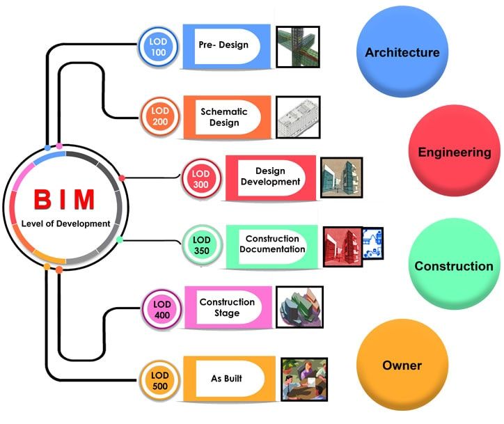
LOD defines the stages of development from conceptual design to as-built models. Each level (LOD 100 to LOD 500) corresponds to an increased amount of geometric and informational detail, providing a clear structure for building and managing BIM models across projects.
There are six levels of development, namely, LOD 100, LOD 200, LOD 300, LOD 350, LOD 400, LOD 500.
1. LOD 100 - Conceptual Design
At LOD 100, the model would consist of overall building massing and the downstream users are authorised to perform whole building types of analysis (volume, building orientation, cost per square foot, etc.)
2. LOD 200 - Schematic Design
Here, the model would consist of "generalised systems or assemblies with approximate quantities, size, shape, location and orientation." Authorised uses would include "analysis of selected systems by application of generalised performance criteria."
3. LOD 300 - Design Development
The Model Element is graphically represented within the Model as a specific system, object or assembly in terms of quantity, size, shape, location, and orientation. Non-graphic information may also be attached to the Model Element.
4. LOD 350 - Construction Documentation
It includes model detail and elements that represent how building elements interface with various systems and other building elements with graphics and written definitions.
5. LOD 400 - Fabrication and Assembly
Model elements are modelled as specific assemblies, with complete fabrication, assembly, and detailing information in addition to precise quantity, size, shape, location, and orientation. Non-geometric information about the model elements can also be attached.
6. LOD 500 - As-Built
Elements are modelled as constructed assemblies for maintenance and operations. In addition to actual and accurate size, shape, location, quantity, and orientation, non-geometric information is attached to modelled elements.
To better understand this, let’s look at the process of detailing a structural kicker. This example has been taken from the book - “BIM and Construction Management” 2nd edition.

- A structural engineer could draw the beams and kickers at LOD 100 in plan view and another LOD 100 detail in elevation.
- The structural engineer could use a hybrid approach where he models the beams at LOD 200 or 300, but uses LOD 100 to annotate the locations of the kickers in plan view and the LO D 100 detail in elevation.
- The structural engineer could model both the beams and the kickers, but place the kickers in the correct location but at a general angle (LOD 200).
- The structural engineer could model both the beams and kickers at LOD 300 (or better) and use the parametric capabilities of BIM to automatically generate an elevation view equivalent.
Also Read: Top 7 Places to Learn BIM (Building Information Modelling) in India
Conclusion
Understanding BIM Level of Development (LOD) is critical for professionals in architecture, engineering, and construction (AEC). LOD standardization promotes reliable and accurate BIM models, improving communication and project outcomes. By adopting LOD, teams can streamline workflows, reduce mistakes, and save time and costs during project execution. To further enhance your BIM expertise, consider enrolling in the BIM Course for Architects offered by Novatr, where you will gain practical knowledge and hands-on experience with industry-leading tools. Visit our resource page for more insights into BIM trends and best practices.
FAQs
1. What is LOD and LOI in BIM?
LOD (Level of Development) refers to the degree of reliability and completeness of information in a Building Information Model (BIM). It outlines how much and what type of data can be relied upon at different project stages. LOI (Level of Information) pertains to the quantity and quality of data provided for each BIM element.
2. What is LOD 200 and LOD 300?
LOD 200 involves generalized representations with approximate quantities, sizes, and locations of the model’s components. As the model progresses to LOD 300, it provides more precise details of components, including accurate size, shape, and location, enabling detailed design and coordination for effective construction planning.
3. What is Level 4 of Detail in BIM?
Level 4 of Detail typically falls under LOD 350, where the model components are highly detailed and represent specific construction documentation. This stage includes detailed representations of how various systems (HVAC, electrical, etc.) integrate into the structure, providing all necessary information for fabrication and assembly in the construction phase.
4. What are the levels of BIM development?
The five levels of BIM development (LOD) are structured to enhance project accuracy. LOD 100 involves basic conceptual designs, LOD 200 provides schematic designs, LOD 300 focuses on detailed design, LOD 350 offers construction documentation, and LOD 500 represents as-built models for operational use, ensuring comprehensive project documentation and coordination.
5. What are the 5 levels of BIM?
The five BIM levels of development (LOD) include: LOD 100 (conceptual design with massing), LOD 200 (schematic design with approximate dimensions), LOD 300 (detailed design), LOD 350 (construction documentation with interfaces), and LOD 500 (as-built conditions for facility management). Each LOD represents different stages of detail and reliability in the BIM process.

 Thanks for connecting!


.png)
