 Thanks for connecting!


Thet Hnin
5 min read
December 22, 2022


Table of Contents

Despite the lack of such details, isometric drawings or an isometric sketch are still relevant and useful in architecture. Let’s find out more about isometric architectural drawings and how you can use them in your projects.
Isometric drawing is a method of representing 3D objects in 2D using equal scale on all three axes. Unlike perspective drawings, it avoids distortion and maintains clarity, making it widely used in architecture and engineering.
What is An Isometric Drawing?
An isometric drawing is a type of axonometric drawing where the X, Y, and Z axes are scaled equally. Derived from the Greek term “equal measure,” it ensures no distortion because all sides are shortened equally. Non-vertical lines are drawn at 30° from the horizontal, which is why no true horizontal lines exist in an isometric sketch.
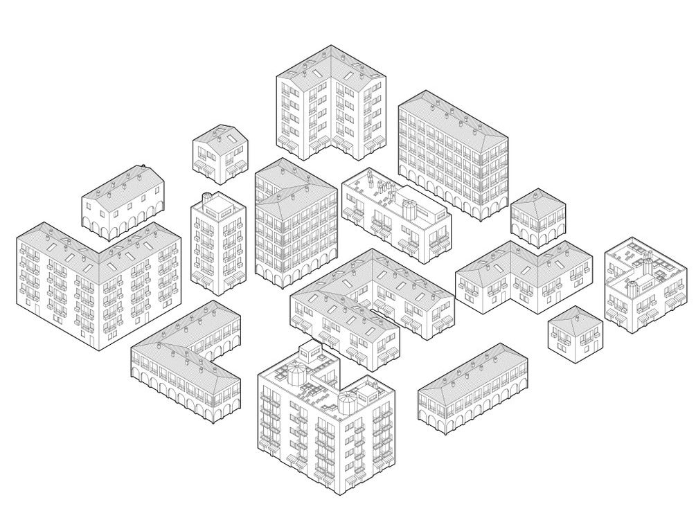
It is a paraline drawing with all the lines parallel to the principal axes drawn at real lengths and the same scale (Ching. F.D.K, 1995, A Visual Dictionary of Architecture). Any non-vertical lines are constructed at an angle of 30 degrees from the horizontal axis. Interestingly, this means there is no horizontal line in an isometric drawing of a building or any structure.
Read more: Benefits of emerging Computational design developments in the AEC industry
Principles of Isometric Drawing
To create accurate isometric architecture drawings, designers follow these rules:
-
Equal Foreshortening: Length, breadth, and height scale equally.
-
Isometric Axes: X and Y set at 30° to horizontal, with Z vertical.
-
Isometric Scale: Converts real dimensions to isometric equivalents.
-
Parallel Lines: Always remain parallel, aiding measurement.
-
Isometric Grid: Often used for hand-drawn isometric sketches.
Difference Between Isometric View and Isometric Projection
Isometric View
An isometric view shows a 3D object from a corner, with axes at 30°. Unlike perspective, lines do not converge at vanishing points.
Isometric Projection
An isometric projection is the graphical method itself, creating depth and accuracy by keeping dimensions at a uniform scale.
Types of Isometric Drawings
1. Mechanical
Shows the arrangement of machine parts and system integration.
2. Plumbing
Depicts water flow, valves, fixtures, and connections.
3. Piping
Guides pipe installation, material listing, and clash prevention.
4. Electrical
Shows switches, outlets, fixtures, and circuit flow.
Benefits of Isometric Drawings
Isometric architectural drawings help architects visualize designs, hide unwanted details, and present clean visuals. In engineering, they simplify MEP and structural layouts, supporting communication between designers, clients, and contractors.

Isometric Drawings in Architectural Design
1. Conceptual Design
Used as diagrams to show the site, sun path, or building programs.
2. Exploded Drawings
Reveal interior layouts, circulation, and hidden details.
3. Wayfinding
Work as an infographic map to guide users through spaces.
Isometric Drawings in Engineering
1. MEP Applications
Show plumbing and systems layouts for contractor reference.
2. Structural Applications
Depict facades, roofs, and frame connections in 3D clarity.
How to Create an Isometric Drawing (Step by Step)
Choose software (Revit, AutoCAD, Illustrator).
Activate isometric grid or isodraft mode.
Select isoplane (left, right, or top).
Use ellipse/polyline tools for curves.
Adjust camera angles for 3D clarity.
Isometric Drawing Examples
Artists and architects often use isometric sketches creatively. Andrew Degraff’s Unfinished Construction Sites highlighted building processes, while Mauco’s illustrated London map showed landmarks and wayfinding.
Conclusion
Isometric drawings remain a vital tool in both architecture and engineering, combining accuracy with creativity. By applying core principles, choosing the right tools, and avoiding common mistakes, designers can deliver clear, professional visuals. To build expertise, join the Master Computational Design Course by Novatr and explore our resource page for more guides and insights.
FAQs
1. What is an isometric drawing in architecture?
Ans : It’s a 2D method of representing 3D objects using equal scale on all axes.
2. What are the main uses of isometric drawings?
Ans: They are used for conceptual design, wayfinding maps, and construction details in architecture and engineering.
3. Which software is best for making isometric drawings?
Ans: AutoCAD for drafting, Revit for 3D models, and Illustrator for clean presentation diagrams.
4. What is the difference between isometric and perspective drawings?
Ans: Isometric keeps dimensions equal with parallel lines, while perspective shrinks objects toward vanishing points.

.png)
.jpg)